VIC 6560 Video Information
This document is about the video output of the US version of the Commodore VIC-20, generated by the 6560 VIC (Video Interface Chip). Although we describe the US version of the VIC-20 as "NTSC", the video signal produced by the VIC chip is a long way removed from the formal NTSC specification.
Non-NTSC markets use a different version of the VIC, the 6561, which produces output compatible with the PAL standard. Unfortunately, I have access to neither a PAL VIC-20 nor a PAL television/monitor, so I cannot write about that device.
The 6560 is driven by a two-phase 14.31818MHz clock, which is divided by four to get the color sub-carrier frequency of 3.579545MHz. I shall use 'q' to refer to cycles of the 14.31818MHz clock, and 'c' for cycles of the color subcarrier clock. The q clock is also divided by 14 to produce the clock for the 6502 CPU, 'p', at just a smidge over 1.02MHz.
When the 6560 is running normally there is no interlacing, so instead of 30 frames per second consisting of one odd field and one even field we have 60 frames per second all having an identical structure.
Vertical Timing
Each frame consists of 261 lines, the first 9 of which make up the vertical blanking and synchronization field.
Within a line there SHOULD be several different voltages used:
- S - Sync, -286mV
- B - Blanking, 0V
- K - Setup (black), 53.6mV
- V - Video (Luminance [Luma, brightness] + Chrominance [Chroma, color]), 714mV peak
The 6560 only uses S, B and V, but at different voltages.
Each line is 910q in duration. In a perfect world this means that there would be a falling edge from B (Blanking level) to S (Sync level) at every 910th q cycle.
A display line starts with a 54q "front porch" at the blanking voltage, B, then 70q of horizontal synchronization pulse, "HSYNC", at the sync voltage, S, followed by 84q of blanking, color burst, setup etc. Finally, the displayed line is 702q wide, which is followed by the front porch of the next line. 54q front porch + 70q HSYNC + 84q back porch, color burst, etc. + 702q video = 910q.
The front porch at the start of the vertical blanking and synchronization sequence is 34q too long. All through the sequence the B->S falling edges are late by (at least) 34q because of this. In this description I will refer to features of the vertical blank/sync sequence relative to where the horizontal sync (B->S transition) should have occurred.
The VBLANK/VSYNC sequence starts with three lines worth of pre-equalizing pulses, two pulses per HLINE period, for a total of six pulses. The odd pulses are 40q wide, the even ones are 30q wide, and the pulses are spaced 420q apart, with the 420q following the even pulses wrapping round 34q into the next HLINE period because of the extended front porch at the start of VBLANK.
Following these pre-equalization pulses there are three lines of serration pulses, two per line. These pulses are notionally 420q wide negative-going pulses. The start of the first serration is a mess. Instead of an orderly transition from narrow negative going equalizing pulses to wide negative going serration pulses, all with neatly lined-up falling edges, there is a messy glitch, the first pulse is too wide and subsequent serration pulses have their falling edge delayed a further 40q, for a total of 74q out of whack.
At the end of the serration pulses we have three lines of post-equalizing pulses, which are back to being 34q out of alignment with the expected HSYNC position. The odd post-equalizing pulses are 40q wide, and the even are 30q, the same as for the pre-equalizing pulses. The inactive time after the last post-equalizing pulse is shorter than the others by 34q, 386q instead of 420q, so the first display line of the frame starts at the expected time.
Overall, the 910q timing is preserved throughout the whole video
stream, however the distinctly mangled nature of the VBLANK/VSYNC
sequence does mean that some televisions and monitors cannot sync
correctly at the start of the frame:
(Of the four NTSC televisions that I have access to, two of them show this wobbly screen behavior, both while using composite video and the RF modulator. One is a flat-panel television, the other a real CRT television)
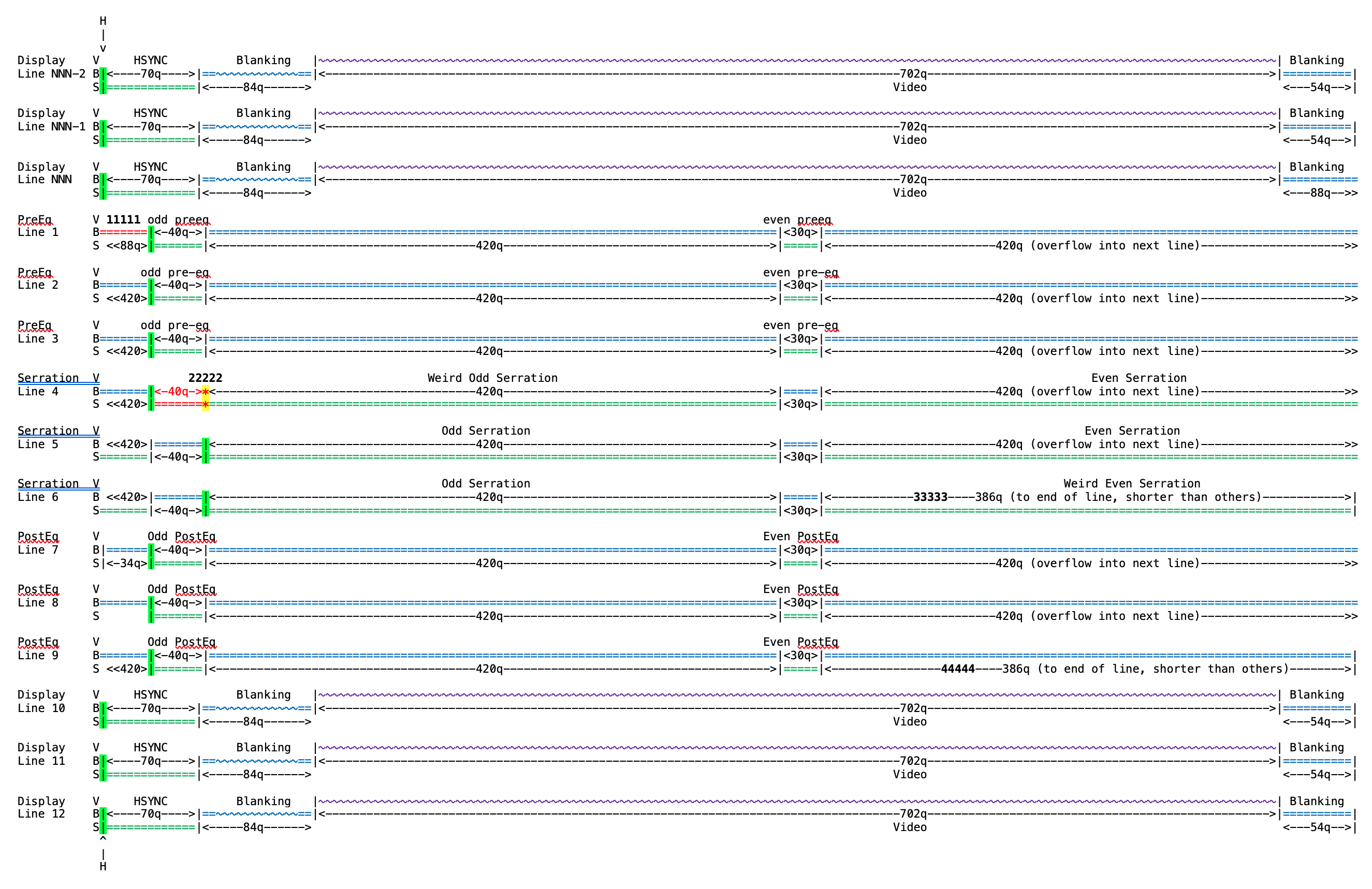
I've depicted the various line types in the following diagram:
Key:
- 'H' - the time when a negative edge should occur on every line for correct horizontal syncing
- 'V' - video level signal
- 'B' - blanking level signal
- 'S' - sync level signal
- 'q' - quad clock, running at 14.31818MHz
Each character in these diagrams represents 5 q-cycles.
=======  this is a steady state signal.
~~~~~~~  this is color burst or video.
<--Xq->  this is the time between two transitions, in 'q' cycles.
<<-----  means the signal continues off the left of the diagram.
----->>  means the signal continues off the right of the diagram.
11111... see footnote.
Normally a diagram of an NTSC signal would start with the front porch, however in this diagram I have drawn it such that each line starts at the position at which the falling edge of the horizontal sync pulse should occur. The actual transitions are highlighted in green.
Vertical Timing Footnotes
- 11111
An unnecessary 34q shift is introduced at the start of the VBLANK/VSYNC sequence, at the start of Line 1. - 22222
This is a glitch, usually a sign that the composite CSYNC signal is constructed with either an XOR or XNOR gate from a VSYNC and an HSYNC source. - 33333
The last Serration pulse is shorter than the expected 420 q-cycles. - 44444
The last post-equalizing pulse is shorter than the expected 420 q-cycles; this moves the HSYNC pulse position back into line with where it was before the start of the VSYNC sequence.
Horizontal Timing
Each display line has the following format:
- The front porch, at blanking level B, for 54q
- The HSYNC pulse, at synch level S, for 70q
- The back porch:
- The start of the back porch, at blanking level B, 12q
- The color burst, 16 cycles at frequency c, 64q
- The end of the back porch, at blanking level B, 8q The total back porch duration is 12 + 64 + 8 = 84q
- The video signal for the line, 702q
In NTSC, the 'end of the back porch' segment is at the black level, K, and is described as the 'setup' period. The 6560 outputs the blanking level B during this period.
Here is a diagram of the back porch area. I do not know what the
significance of the glitch before the color burst is.
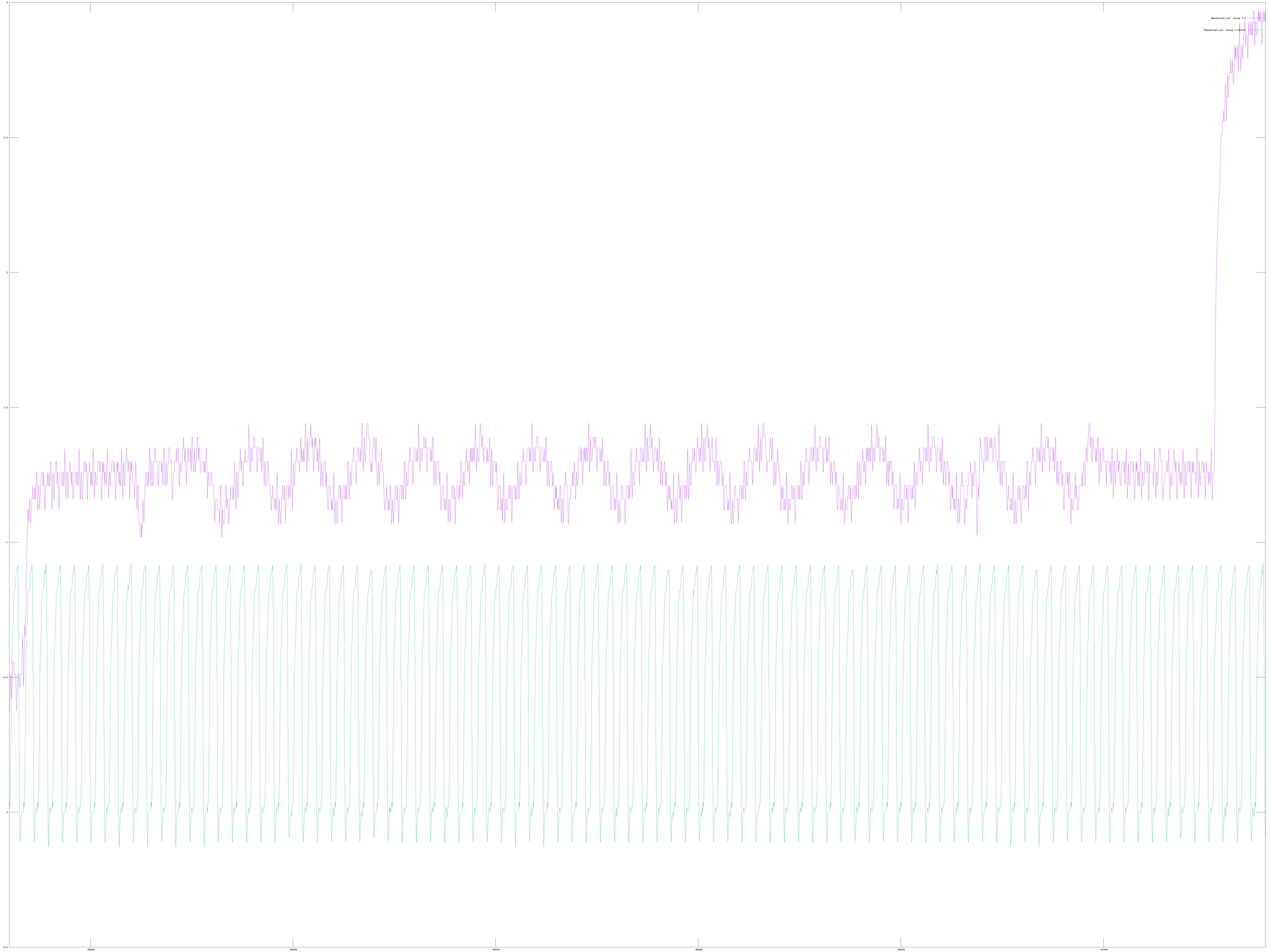
There is, however, something unusual happening in the video stream
from the 6560. If you overlay two consecutive lines of video, you get
the following:
This clearly shows that the 6560 is shifting the phase of the color burst and chroma by 180° on consecutive lines, so what's going on? Is the 6560 generating PAL video? No. The color burst at the start of each line is generated from the c clock, but the line frequency, H, is an odd multiple of the c clock so the color burst, although always in phase with the c clock, appears to alternate by 180° from line to line.
Pixel Data
The displayed video for each line consists of a left margin, the active display data for that line, and the right margin.
The active display data is (usually) 22 columns of characters, each of which is 8 pixels wide. For each character, the 6560 performs two memory fetches, the first to obtain the color information and the character code from the video memory, and the second to obtain the bits representing this line of the displayed character from the character generator ROM.
Each of these fetches is interleaved with the 6502's memory accesses, and so it takes 2 p cycles to fetch all the information to display for a single character. Remembering that the p clock is obtained from the q clock by dividing by 14, then each character takes 2 * 14 = 28q to display. 22 columns * 28q per column gives 616q of character data being displayed per line, and 702 - 616 = 86q to be split between the left and right margins. Given that each character takes 28 q clocks to display, and is 8 pixels wide, we find that each pixel takes 28 / 8 = 3.5 q clocks. 3.5 clock cycles is an unusual number, rarely used in digital circuits, and at first glance appears to be inconvenient to generate from a single 14.31818 MHz clock, however the q clk coming into the 6560 is actually a pair of two-phase non-overlapping clocks, so if you make use of the rising edges of both the Phi1 and Phi2 incoming clocks then each pixel is 7 (Phi1 OR Phi2) edges, which is much easier to work with.
Interlaced vs. Non-Interlaced
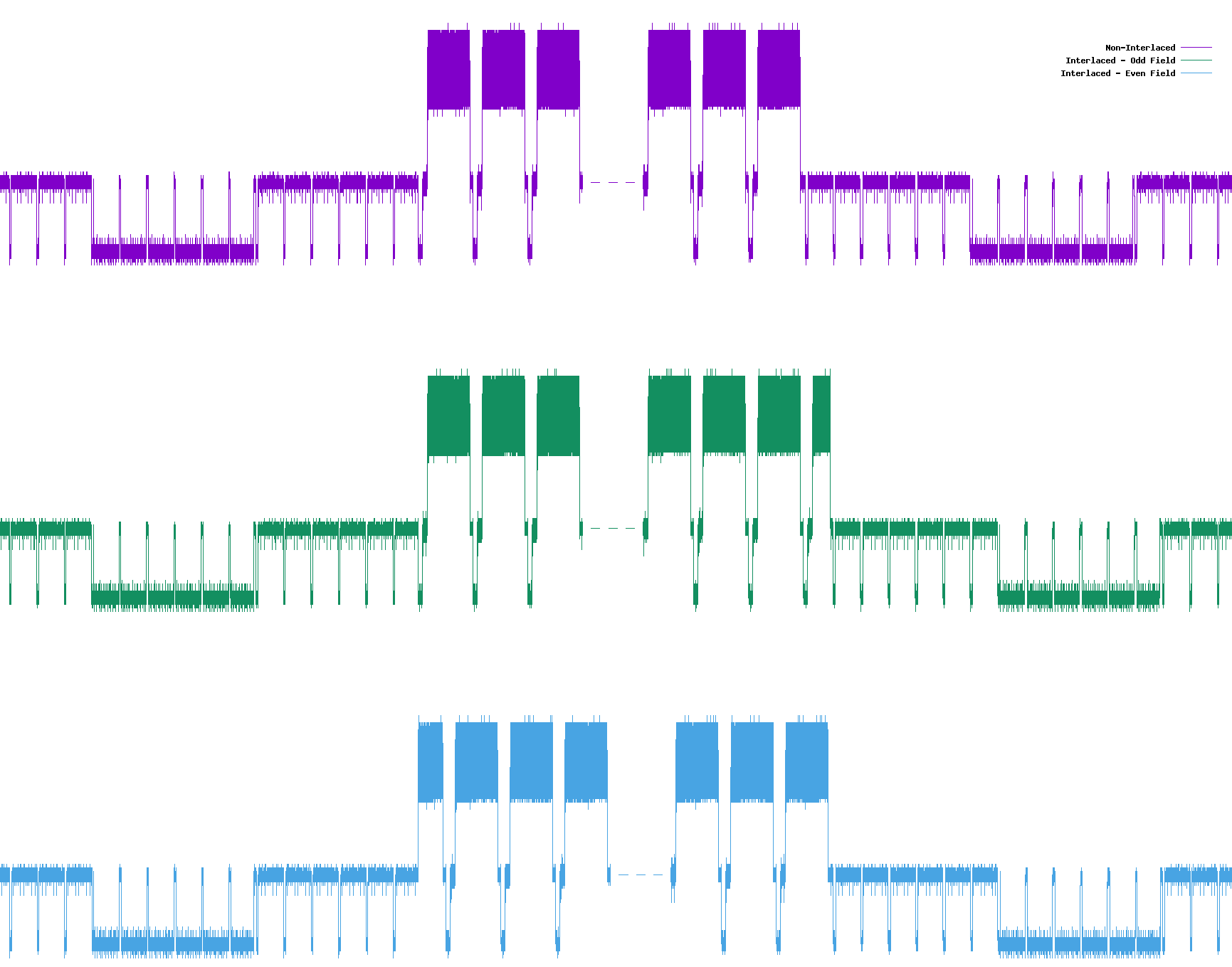
Setting bit 7 of 6560 register $9000 to 1 enables interlaced scanning. When interlacing is enabled two fields are generated per frame, an odd field and an even field. The information displayed in each field of the frame is identical (unless updated in video memory between consecutive fields), unlike normal NTSC television where the two fields each contain half of the video and when overlapped they represent the full picture. When interlaced mode is enabled an extra line-and-a-half is added to each field compared to non-interlaced operation. For odd fields the extra half line appears at the end of the field, for even fields it appears at the start of the field:
6560 Registers
The following 6560 registers directly manipulate the timing of the image displayed:
$9000[7] Enable Interlacing - Default 0
See the section on Interlacing, above.
$9000[6:0] Horizontal Position - Default 5
This field sets the timing for the left margin of the text display. Increasing this value by 1 moves the display region right by 4 pixels. The number of q cycles for the left margin is 1 + 14 * N, where N is the value from $9000[6:0]. If $9000[6:0] is set to zero, then the last scan line of the display is distorted. when $9000[6:0] reaches 18 then there is distortion to the displayed lines.
$9001[7:0] Vertical Position - Default 25
This register sets the timing for the top margin of the text display. Increasing this value by 1 moves the display region down by 2 raster lines. The default value 25 yields 40 raster lines for the top margin. The number of raster lines for a value V is V * 2 - 10. Values below 4 corrupt the VSYNC/VBLANKING pulses. A value of zero also corrupts the very last raster line of the display.
$9002[6:0] Number of Columns - Default 22
This field sets the number of columns of displayed text. Increasing the value by 1 increases the number of displayed characters per line by 1.
$9003[6:1] Number of Lines - Default 23
This field sets the number of rows (lines) of displayed text. Increasing the value by 1 increases the number of lines of text displayed by 1.
Color
Color encoding in NTSC video is a little awkward - it was added after the original NTSC spec was in general use across the US, and so had to be added to what was already there. This was achieved by superimposing the color information into the luminance signal.
After the horizontal sync pulse, in the back porch, there is a "color burst", 16 cycles at frequency c. This is used to set the receiving device's notion of the subcarrier frequency, and most importantly, the phase of the color subcarrier.
The luminance signal is modulated with a sine wave - the frequency of this modulation is always c, but the color being represented is indicated by the phase shift of this sine wave relative to the color burst. The amplitude of the sine wave governs the color saturation, and the mean value of the sine wave above the blanking level, B, sets the brightness - so a black and white receiver can still display the image as the higher frequency color information will be filtered out.
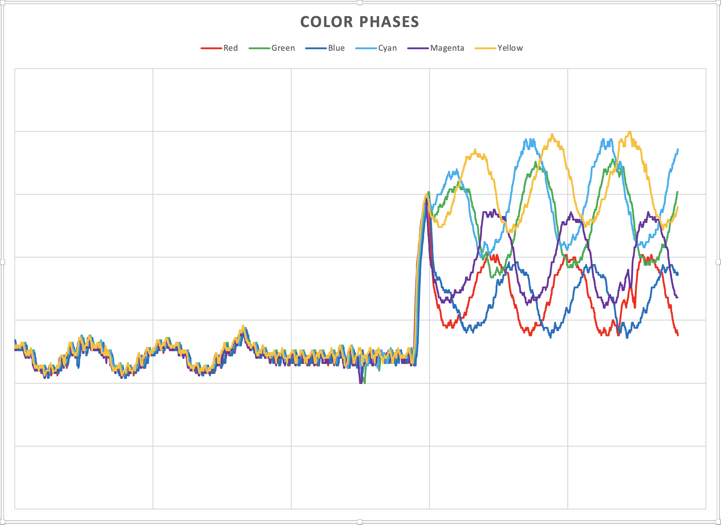
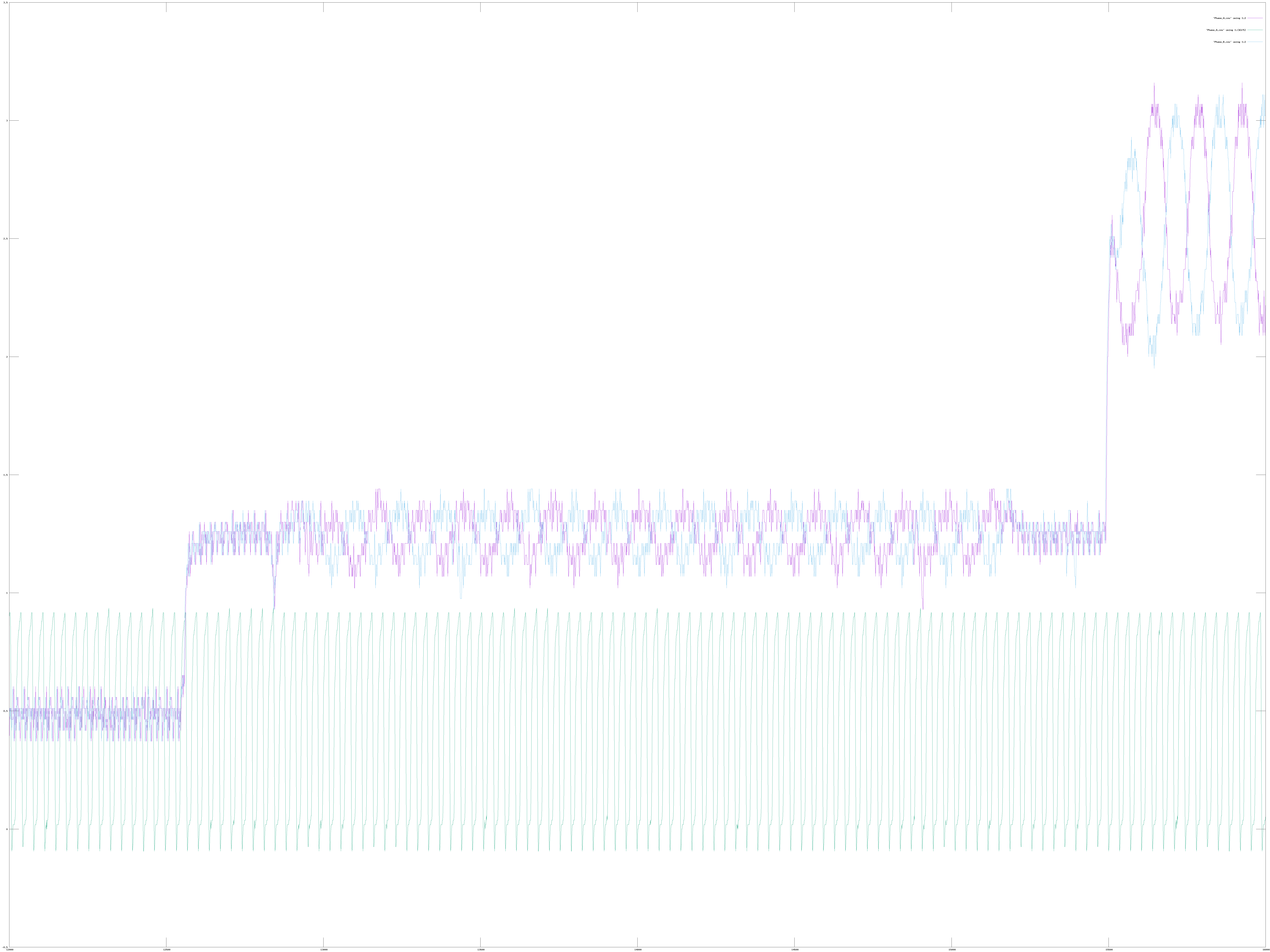
In the above diagram each of the lines represent the corresponding signal that is produced when the whole screen is that color on my VIC-20 - this diagram is six separate traces overlaid to show the relative phases and amplitudes of the color information. I have omitted black, which would be an unmodulated continuation of the blanking level, and white, which is an unmodulated constant high output.
To the left, all the signals overlap during the color burst (the three sine wave cycles) and the last part of the back porch. During the display part of the line each signal is at the same frequency as the initial color burst, but with a shifted phase.
Note also that the average amplitude of the different color signals varies - yellow being the highest magnitude, and blue the lowest. In the standard color bars test pattern, the bars are laid out left to right in increasing order of brightness, such that when they are viewed on a black and white receiver the shades of gray progress from solid white on the left to solid black on the right. You can see in the diagram that the color order should be (white), yellow, cyan, green, magenta, red, blue, (black).
The amplitude of the modulating sine wave sets the saturation of the color. For this diagram each of the colors was fully saturated, so this modulation amplitude is approximately the same for each color.
The color phase shifts that are used by the VIC-20 are in the following table, along with the luminance value used for that color.
| Color | Phase Angle | Luminance |
|---|---|---|
| Black | N/A | 0.0 |
| White | N/A | 1.0 |
| Blue | 0° | 0.25 |
| Lt Blue | 0° | 0.50 |
| Purple | 45° | 0.50 |
| Lt Purple | 45° | 0.75 |
| Red | 112.5° | 0.25 |
| Lt Red | 112.5° | 0.50 |
| Orange | 135° | 0.50 |
| Lt Orange | 135° | 0.75 |
| Yellow | 180° | 0.75 |
| Lt Yellow | 180° | 1.00 |
| Green | 225° | 0.50 |
| Lt Green | 225° | 0.75 |
| Cyan | 292.5° | 0.75 |
| Lt Cyan | 292.5° | 1.0 |
Acknowledgements
I have obtained information from many sources such as data sheets and specifications, including the original NTSC document ("14.31818 mega cycles") and the 6560-6561 datasheet. Much of the information here has been obtained first-hand using a 'scope and a logic analyzer. However, some of it did come from other people, in particular I'd like to thanks the following members of the 'Denial' forums at http://sleepingelephant.com/ipw-web/bulletin/bb/index.php for their inspiration.
- Lance Ewing - his analysis of the 6561 has been invaluable
- Mike - general hints and nudges to push me in the right direction
- tokra - just awesome hi-res work which I look forward to testing against.